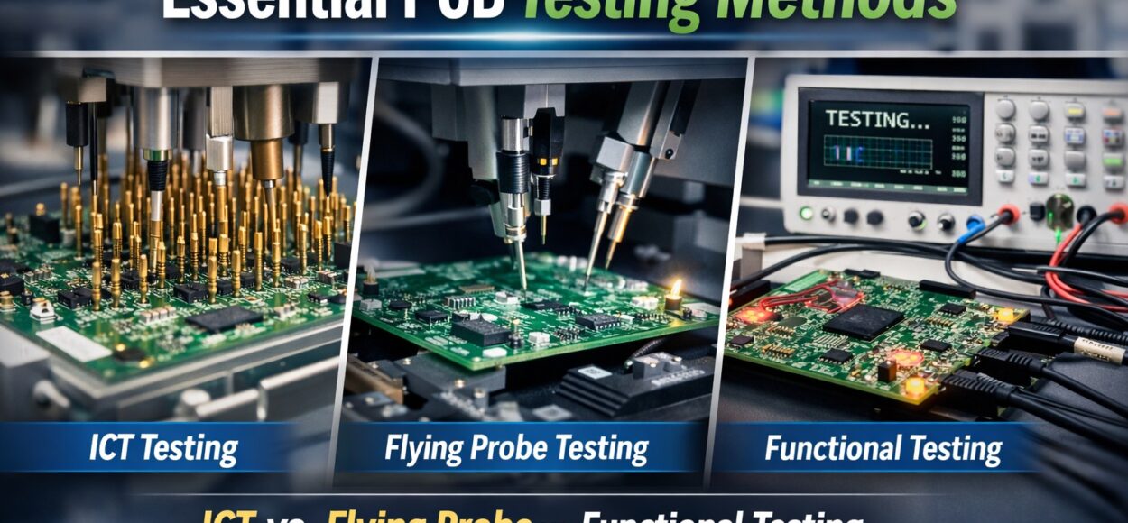
Essential PCB Testing Methods: ICT vs. Flying Probe vs. Functional Testing
Printed Circuit Boards (PCBs) form the backbone of virtually every electronic device. Yet a PCB is only as reliable as its testing process. Without robust testing, latent defects can lead to failures in the field, costly recalls, and damage to brand reputation.
In this article, we’ll break down the three most widely used PCB testing methods – In-Circuit Testing (ICT), Flying Probe Testing, and Functional Testing. We’ll explore how each works, when to use it, pros and cons, and how to choose the right approach for your specific project.
Why PCB Testing Matters
PCB assembly is a complex multi-step process. Soldering, component placement, and material tolerances all introduce opportunities for defects. Testing ensures:
- Connectivity is correct (no open/short circuits)
- Components are correctly placed and oriented
- Assembly quality is within specification
- Functional performance meets design requirements
- Testing isn’t a luxury – it’s a critical part of quality assurance and product reliability.
1. In-Circuit Testing (ICT)
Overview:
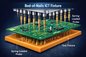
In-Circuit Testing (ICT) is a high-speed method used to electrically test a fully assembled PCB by physically contacting test points with spring-loaded pins in a bed-of-nails fixture.
How ICT Works
- The PCB is placed into a custom fixture.
- Spring-loaded probes make contact with test points.
- A controlled signal checks:
- Resistors, capacitors, inductors
- Diodes and transistors
- ICs (to verify presence and orientation)
- Reports errors such as shorts, opens, incorrect components.
Strengths
- Fast, repeatable, extremely thorough for assemblies with test points.
- Excellent for high-volume manufacturing.
- Detects most board-level assembly faults early.
Limitations
- High fixture cost – custom fixtures may cost thousands of dollars.
- Fixture development takes time.
- Not ideal for advanced BGAs or boards without accessible test points.
Best Use Cases
- Mid to high volume production
- Boards with clearly defined test pads
- When lowest possible cost per unit (over time) matters
2. Flying Probe Testing
Overview:
Flying Probe Testing uses multiple movable probes that “fly” across the board to test electrical nets without a custom fixture.
How Flying Probe Works
- PCB is placed on a stable platform.
- Probes move in X/Y/Z axes to contact nodes on the board.
- Software sequences tests for:
- Continuity (opens/shorts)
- Component values
- Diode/LED verification

Strengths
- No costly fixtures – excellent for low to medium volume production.
- Flexible – can adapt to new designs quickly.
- Great for prototype testing and early design validation.
Limitations
- Slower than ICT due to sequential probing.
- Limited access may reduce coverage on very dense or multi-layer PCBs.
- Testing depth is less than ICT – harder to identify certain faults.
Best Use Cases
Prototyping and R&D
Low volume production
Designs with frequent revisions
3. Functional Testing
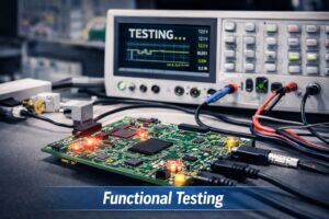
Overview:
Functional Testing evaluates a PCB by powering it and verifying it performs its intended real-world function.
How Functional Testing Works
- Test conditions mimic real operational environment.
- Power is applied, and device behavior is measured.
- Tests may include:
- Digital signal verification
- Analog performance
- Communication interface checks
Strengths
- Confirms that the board works as designed under real conditions.
- Detects issues that ICT or flying probe can’t, such as firmware or timing errors.
Limitations
- Requires custom test development – time-consuming.
- Not a substitute for electrical integrity testing.
- Can be expensive if many test sequences are needed.
Best Use Cases
- Final quality check before product integration
- Products with complex behavior (embedded systems)
- Safety-critical applications