- November 24, 2025
- PCB Blog
How to Perform a Thermal Analysis on Your PCB
Techniques for Heat Dissipation & Thermal Management
Heat is one of the most common causes of electronic failure. When a PCB overheats, it can lead to:
- Damaged components
- Shortened product lifespan
- Performance drops
- Safety hazards
- Costly product recalls
This is why thermal analysis is a critical step in PCB design and manufacturing – especially for high-density, high-power, and mission-critical electronics.
In this guide, we explain what thermal analysis is, why it matters, and the best techniques to evaluate and manage heat on your PCB. Whether you’re building power electronics, embedded systems, LED boards, or compact IoT devices, strong thermal design ensures reliability and long-term performance.
What Is Thermal Analysis in PCB Design?
Thermal analysis is the process of evaluating how heat is generated, distributed, and dissipated within a PCB. It helps engineers:
* Identify heat sources
* Predict temperature rise
* Prevent component overheating
* Optimize layout and materials
* Improve long-term reliability
Most thermal analysis is done using simulation tools, but real-world physical testing is equally important.
Why Thermal Analysis Matters
Heat affects both performance and reliability. Without proper thermal engineering, PCBs may experience:
- Component derating
- Solder joint cracking
- Track delamination
- Power losses
- Complete circuit failure
Industries where thermal reliability is critical:
- Automotive electronics
- Industrial equipment
- Power supplies
- LED lighting
- Avionics and defense
- High-speed networking
- EV battery systems
Key Steps to Perform Thermal Analysis on Your PCB
Below are the essential stages of a full thermal evaluation.
1. Identify the Heat Sources
Heat mainly comes from:
- Power conversion ICs
- CPUs, GPUs, FPGAs
- MOSFETs and power transistors
- Voltage regulators
- High-current traces
- LED arrays
Use component datasheets to check:
- Thermal resistance (θJA, θJC)
- Maximum junction temperature
- Power dissipation ratings
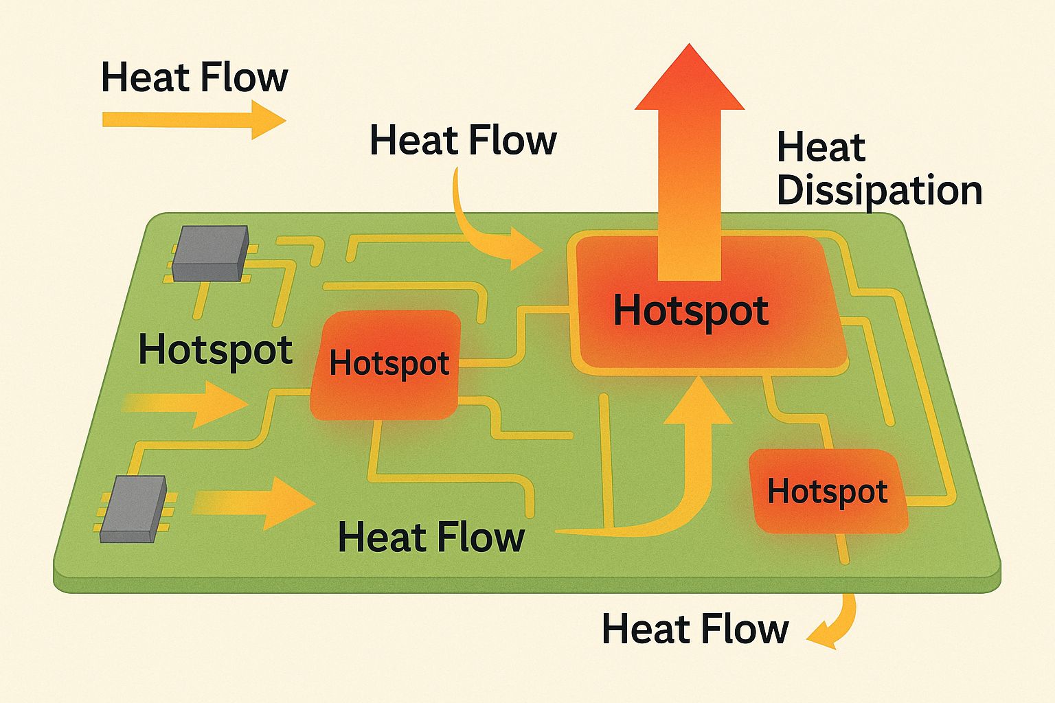
2. Analyze Heat Flow Paths
Heat travels through:
- PCB copper
- Dielectric material
- Vias
- Components
- Enclosure
Understanding conduction, convection, and radiation is key to knowing where heat accumulates.
3. Use Thermal Simulation Software
Thermal simulation tools (e.g., ANSYS, Altium, SolidWorks, Icepak) let engineers model:
- Component temperature
- Heat distribution
- Airflow
- Layer stacking impact
- Via effectiveness
- Cooling strategies
Simulations help predict thermal performance before fabrication.
4. Improve PCB Layout for Thermal Balance
A thermally optimized PCB layout reduces hotspots and improves heat spreading.
Best practices:
- Keep heat-generating components apart
- Place sensitive ICs away from heat sources
- Orient components for airflow
- Use symmetrical heating distribution
5. Add Thermal Vias & Copper Pour Areas
Thermal vias help transfer heat through layers. Use:
- Via arrays under hot components
- Copper planes for heat spreading
- Thicker copper (1–2 oz) for power boards
- Via-in-pad for direct heat dissipation
6. Select Heat-Efficient Materials
Choosing the right materials improves thermal performance.
Key materials:
- High-Tg laminates (170°C+)
- Aluminum-based PCBs (for LEDs)
- Metal-core PCBs
- FR-4 with improved thermal conductivity
- Ceramic substrates for extreme heat
7. Add Heat Sinks, Heat Spreaders & Cooling Systems
For high-power boards:
- Heat sinks extract heat from components
- Heat spreaders distribute heat evenly
- Heat pipes help move heat to cooler areas
- Fans enable forced convection
- Thermal pads/paste improve surface contact
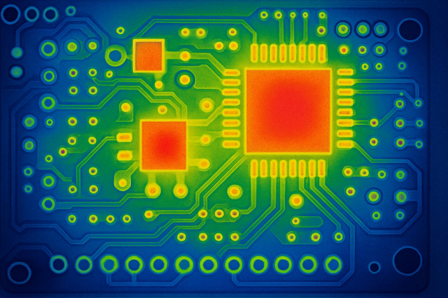
8. Validate Using Real-World Testing
After simulation and fabrication:
- Use thermal cameras
- Perform temperature rise tests
- Check airflow patterns
- Evaluate performance under load
- Compare results to simulation
Validation ensures the board performs reliably in real-world conditions.
Advanced Thermal Management Techniques
Optional strategies for advanced or high-power designs:
- Embedded copper coins
- Graphite heat spreaders
- Liquid cooling channels
- Heavy copper PCBs (>3 oz)
- Stacked thermal vias
- Microvia HDI heat dissipation
Common Thermal Problems and Solutions
| Problem | Cause | Solution |
|---|---|---|
| Hotspots | Concentrated power | Add copper planes, vias |
| Component overheating | Poor placement | Move components, add heatsink |
| Delamination | Excess heat buildup | Use high-Tg laminate |
| Signal noise | Thermal gradients | Balance layout + copper spreading |
| System throttling | CPU/GPU heating | Active cooling or better spreaders |
Frequently Asked Questions (FAQ)
If components run too hot, the board exhibits instability, or your thermal tests show hotspots above limits, your PCB has thermal issues.
Most components run safely between 40–85°C, while high-power devices may reach 100–125°C depending on specs.
No – real-world thermal testing must follow simulation to account for environmental and assembly differences.
Use heat sinks on power components, LED drivers, MOSFETs, CPUs, and regulators where power dissipation is high.
Yes – thicker copper layers and more layers improve thermal dissipation significantly.