
The Future of Flexible & Rigid-Flex PCBs
How flex circuits are reshaping wearables, aerospace, and medical applications.
As products become smaller, lighter, and smarter, circuit boards are evolving too. Flexible and rigid-flex PCBs let designers bend, fold, and stack electronics in ways that flat, rigid boards simply can’t. That capability is powering a wave of innovation across wearables, aerospace systems, and medical devices – and it’s only accelerating.
This article explains what flexible and rigid-flex PCBs are, why they matter, how each market is using them, design and manufacturing considerations, and what to ask your PCB partner to succeed on first pass.
Quick definition: Flex vs. Rigid-flex
Flexible PCB (flex): a circuit built on bendable substrates (polyimide, thin PET) that can be folded, wrapped or flexed repeatedly. Ideal for dynamic motion and tight spaces.
Rigid-flex PCB: a hybrid board that combines rigid sections (for components and connectors) with flexible sections (for interconnects and folding). Great for complex, space-constrained assemblies.
Why it matters: flex and rigid-flex boards reduce size, improve reliability (fewer connectors/cables), and enable new form factors – from a smartwatch strap to a satellite payload.
Why the market for flex and rigid-flex is growing

- Miniaturization and comfort – consumer wearables demand thin, unobtrusive electronics.
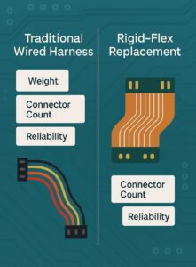
- Reliability & weight – aerospace and portable medical devices need fewer connectors and lighter harnessing.
- Higher integration – rigid-flex boards allow components and antennas to be placed optimally across 3D volumes.
- Advanced materials & manufacturing – improved polyimide laminates, finer traces, and high-precision assembly make flex more affordable
Wearables: fit, feel, and continuous sensing
Use cases: smartwatches, fitness bands, health patches, hearing aids.
Why flex helps:
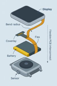
- Enables curved displays and sensors on straps.
- Lets designers route antennas and sensors around the body for better signal and readout.
- Removes bulky connectors – increasing water resistance and comfort.
Key design points:
- Use low-profile components and coverlays to protect bending zones.
- Define bend radii and dynamic vs. static flex zones early.
- Consider biocompatible adhesives and coatings for skin-contact devices.
Manufacturing notes: repeated bending requires controlled materials (flexible copper foils, reinforced stiffeners) and lifecycle testing (bending fatigue cycles).
Aerospace: lighter, denser, mission-ready electronics
Use cases: avionics harness replacements, satellite instrument arrays, UAVs.
Why rigid-flex is valuable:
- Reduces cable weight and potential failure points – critical for flight and space.
- Packs complex functionality into 3D volumes where space is premium.
- Improves vibration and thermal resilience when designed to aerospace tolerances.
Key design & regulatory considerations:
- Specify materials and finishes that meet aerospace temperature, outgassing, and vibration specs.
- Plan for redundancy and maintainability – e.g., test points and modular rigid sections.
- Work with a fabricator experienced in trace impedance control, microvias and flight-grade materials.
Medical: small, sterile, and safety-critical
Use cases: implantables (where used), wearable monitors, diagnostic probes, surgical tools.
Why flex/rigid-flex matter:
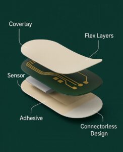
- Low-profile interconnects and conformal circuits fit anatomy and surgical instruments.
- Fewer connectors mean easier sterilization and lower infection risk.
- Flexible sensors enable continuous, long-term monitoring (ECG patches, glucose monitors).
Design and compliance tips:
- Choose biocompatible coverlays and adhesives where in contact with skin or fluids.
- Plan for sterilization cycles (autoclave, EtO, gamma) as required – select materials accordingly.
- Document design controls and traceability for regulatory submissions (e.g., FDA U.S. medical device pathways) when applicable.
Key design rules for flex & rigid-flex success
- Define bending rules early – separate static (once-folded) vs. dynamic (repeated flex) zones and specify minimum bend radii.
- Avoid components in high-flex areas – confine parts to rigid sections or use strain-relief stiffeners where needed.
- Use appropriate copper and coverlay – flex copper weight and polyimide coverlays affect durability.
- Plan for testability – include test points, PTH anchors in rigid areas, and clear DFT/DFM notes.
- Thermal & stress analysis – consider thermal expansion and mechanical stress, especially in high-temp or vibration environments.
Fabrication & assembly realities
- Tooling and handling: flex boards are delicate – require specialized routing, tooling, and storage to avoid creases or contamination.
- Assembly processes: reflow profiles, solder types, and adhesive dispensing must be tuned for flex substrates.
- Yield & cost: first-article engineering can be costlier, but production yields improve with design-for-manufacture (DFM) iterations.
- Supplier selection: choose a partner with rigid-flex experience, IPC knowledge, and controlled processes for handling flex materials.
Reliability testing you should require
- Bend/flex cycle testing (dynamic fatigue).
- Thermal cycling and thermal shock.
- Vibration and shock tests, especially for aerospace/automotive.
- Humidity and ingress tests (IPX/biological compatibility for medical wearables).
- Electrical testing (continuity, impedance, high-voltage isolation where relevant).
Cost considerations & when flex makes sense
- Higher NRE/prototype costs – specialized tooling and material costs.
- Lower system cost – reduced cables/connectors and smaller enclosures can offset board costs.
- Volume matters – economies improve at mid-to-high volumes, but even low volumes benefit when the system form factor is critical.
Decision rule of thumb: choose flex/rigid-flex when form factor, weight, reliability, or assembly simplification provide measurable system benefits.
FAQs
Q1. What’s the difference between flex and rigid-flex PCBs?
Flex boards are fully bendable. Rigid-flex boards combine rigid component areas with flexible interconnects, offering both stability and folding capability.
Q2. How long do flex circuits last with repeated bending?
Lifespan depends on material, copper weight, bend radius and coverlay. Properly designed flex circuits can handle millions of cycles in static or limited dynamic use. Always perform application-specific fatigue testing.
Q3. Are flex PCBs compatible with high-speed signals?
Yes – with correct stack-up, impedance control and careful routing, flex and rigid-flex can support high-speed interfaces and RF antennas.
Q4. Do flex boards need special assembly equipment?
Yes – handling, reflow profiles, and adhesive application differ from rigid boards. Choose assemblers experienced with flex/rigid-flex.
Q5. Can flex PCBs be sterilized for medical use?
Some materials and adhesives tolerate common sterilization methods, but you must validate materials and processes per the required sterilization protocol.
Q6. What design files should I provide to the fabricator?
Complete Gerbers/OA/BOM, clear layer stack-up, bend lines, coverlay outlines, stiffener location, DFM notes, and test procedures.
Q7. Are rigid-flex boards more expensive than rigid PCBs?
Per-board fabrication cost is typically higher, but system-level savings (reduced harnessing, assembly) often make them cost-effective.
Q8. How do I test a folded rigid-flex assembly?
Test rigid sections electrically; include continuity tests across flex regions and perform environmental/fatigue tests on assembled, folded units.
Ready to design the next generation of compact, reliable electronics?
If your product needs to be lighter, smaller, or fold into a 3D shape, flex and rigid-flex PCBs are often the right choice – but success depends on early design decisions and an experienced fabrication partner.
Precision4PCB offers engineering support, stack-up planning, and rigid-flex fabrication to help you reach first-pass success.

Final thought
Flexible and rigid-flex PCBs are no longer niche – they’re enabling product designs that were impossible a decade ago. The technical payoff is real, but it requires early planning, the right materials, and a manufacturing partner who understands the subtleties of bending, assembly, and testing.