
- May 25, 2026
- PCB Blog, PCB Design
Designing PCB Stackups for High-Speed Digital and RF Performance
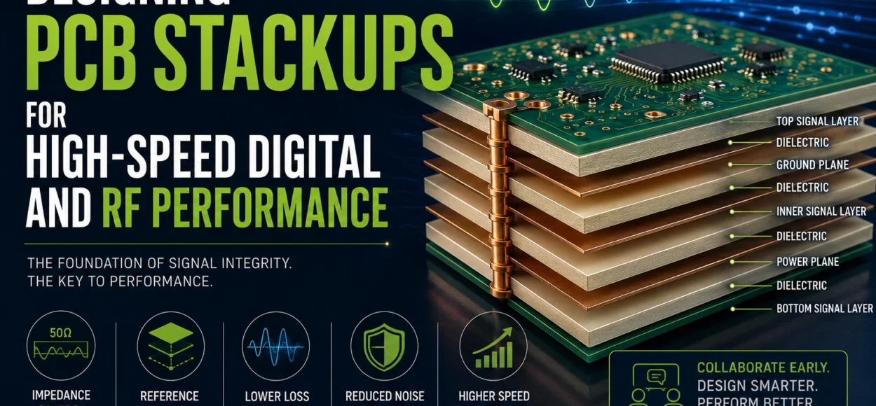
As digital speeds climb into multi-gigabit territory and RF designs push deeper into microwave frequencies, PCB stackup design has become one of the most critical elements of successful electronic systems. While many engineers focus primarily on routing and component placement, the truth is that signal integrity is often determined long before the first trace is drawn. It begins with the stackup.
A well-designed stackup establishes the electrical environment in which signals travel. Layer order, dielectric spacing, copper weights, and reference planes all influence impedance, signal loss, and electromagnetic behavior. In high-speed and RF designs, poor stackup decisions can introduce reflections, crosstalk, and unpredictable signal distortion. These issues often appear only after the prototype is built, when they become significantly more expensive to correct.
Material selection is another key factor. Standard FR-4 works well for many digital applications, but as frequencies increase, its limitations become apparent. FR-4 exhibits higher dielectric loss and variability in dielectric constant compared with specialized high-frequency materials. For RF, microwave, and very high-speed digital circuits, engineers frequently turn to materials such as PTFE-based laminates, ceramic-filled hydrocarbon systems, or other low-loss substrates. These materials provide more stable dielectric properties and significantly lower signal attenuation at higher frequencies.
Dielectric thickness also plays a direct role in impedance control and signal integrity. The spacing between signal layers and reference planes determines the characteristic impedance of traces. Thinner dielectrics typically allow narrower trace widths to achieve a given impedance, which can be valuable for dense designs. However, dielectric thickness must be carefully balanced with manufacturability and isolation requirements. Even small variations in dielectric thickness during fabrication can shift impedance values and affect signal performance.
Reference planes are equally essential. High-speed and RF signals require continuous return paths to maintain signal integrity and minimize electromagnetic radiation. Solid ground or power planes provide these return paths and help contain electromagnetic fields. When reference planes are interrupted by splits, voids, or poorly placed vias, return currents are forced to find alternative paths, increasing noise, crosstalk, and EMI risk.
One of the most effective ways to ensure a successful stackup is early collaboration with the PCB fabricator. Fabricators understand material availability, laminate tolerances, copper thickness variations, and manufacturing constraints that may not be obvious during the design stage. By working together before layout begins, engineers can define stackups that meet electrical requirements while remaining practical to manufacture.
In high-speed and RF PCB design, the stackup is far more than a mechanical layer list—it is the electrical foundation of the entire circuit. Engineers who treat stackup design as a strategic step, rather than an afterthought, dramatically improve signal performance, reduce design iterations, and increase the likelihood of first-pass prototype success.
For more information go to www.precision4pcb.com or call the president Jay Rupani at 847-439-5447 and he’ll be happy to help you out.
FAQs (Frequently Asked Questions)
What is the ideal PCB stackup for high-speed digital and RF designs?
Why is stackup design critical before routing begins?
When should engineers use high-frequency materials instead of FR-4?
How do dielectric thickness and layer spacing affect impedance?
Why is early collaboration with a PCB fabricator important?
Can a PCB expert review my stackup before fabrication?
Yes – working with experienced PCB specialists early in the design phase helps validate stackups, optimize impedance, and ensure your design meets both performance and manufacturing requirements. This significantly improves first-pass success rates.